December 22, 2020
MIT 6.828 Lab 1 Note
Introduction
From today, I am going to share my experience in learning, implementing labs of MIT 6.828 in my blog.
My background knowledge includes: C, computer architecture, RISC-V.
I am going to use 2018 version material simply because there are most amount of resource about this version online.
Environment setup
First clone the course git repo, Course Git reop. Then install toolchain, install instruction. Note that if the Compiler Toolchain is already installed, the only thing needs to be installed is QEMU emulator. Next, lets compile the files in the Git repo.
Then type
We will successfully start JOS in the QEMU emulator. Now we boot the template OS and finish the setup of environment and lets take a look at the memory distribution in 32-bit machine.
PC'S address space & PC start up process
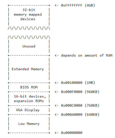
The important part for PC start up is only the lower 1MB part, because right now CPU is under Real mode and the only accessible memory is this part. In this part, the most important on is BIOS (basic IO system), because code in BIOS starts the normal PC start up. And the other part of this 1MB memory is mapped by peripherals, which means CPU can read/write the other part to manipulate peripherals.
An interesting history
The max memory 32-bit processor can handle is 4GB. So when the 64-bit processor came out, larger memory were used in PC. The modern PC usually put BIOS at the top of the memory, and to keep the backward compatibility for some old software, designer keeps a "hole" from 0x000A0000 to 0x00100000.
Use GDB to analyze the process of start up
Now open two terminals, move into the OS folder. In the first one, type
This line starts the emulator and waits for the connection of GDB. And in the second terminal, type
This line starts GDB and connect it to the OS. The file .gdbinit configs GDB to debug the code executed in the boot of OS in QEMU.
Very first instruction
This is the first line appears after we connect GDB and OS. It shows where does the processor fetch the very first instruction and what that instruction is when we boot a PC.
Under the real mode, address is in the form of (segment base : offset). So in the above line, in [f000:fff0], 0xf000 is segment base and 0xfff0 is offset. For 0x3630, 0xf000e05b, 0x3630 is segment base and 0xf000e05b is offset. The way to transfer this form into physical form is:
And after translating, this line means the professor fetch instruction from address 0xFFFF0, and instruction inside is a jump instruction, and the target address is 0xF004 435B.
So there is several natural questions:
- Why did the designer put the very first instruction in this location (distance between here and end of BIOS is 0x100000 - 0xFFFF0 = 16 bytes)?
- Why don't just put this instruction in the beginning of the BIOS?
- Considering it is a jump instruction, why not set the first instruction just at its target address?
The first two questions can be answered together. We have to consider that each PC company has their own BIOS code, user can add BIOS code too. Also, different company designs different length of BIOS boot code, so if the user wants to add code, the place to add is uncertain. However, if instead, we put user created code in the beginning of BIOS, it is more convenient to manage. So normally we put BIOS boot code in the end of BIOS part.
For the last question, because different PC has different length of BIOS boot code, for example, if this code is 1KB, the start address is 0x100000 - 0x400 = 0xFFC00. If the code is 2KB, the start address is 0xFF800. And it is not a good practice to adjust the first instruction address in each PC. So the rule is put a jump instruction at 0xFFFF0 and the target is defined by each company.